 Trolley Scan(Pty) Ltd
Trolleyponder®/EcoTag®
Technical notes - Transmission and reflection of energy
|
The propogation of electromagnetic energy between the reader and the transponder, passing through various bodies, is a complex situation. For the part of the path where the energy travels through air, the energy density available to the transponder drops off as the
square of the distance (every doubling of range requires four times the amount of transmitter energy), and when the energy passes through solid items in the direct path between the reader and the transponder, much of
the energy is reflected off the boundaries of the bodies and never reaches the transponder.
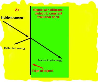
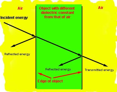
Those engineers who have been involved in the development of short range high resolution radars, such as for detecting fissures in rocks in underground gold/coal mining operations - or for detecting blocks of explosives set in a road - know that the interface where two materials of different dielectric constant meet, causes some of the incident energy to reflect which can then be detected to locate the edge of the saught objects. Due to some of the energy reflecting, a weakened signal continues through the object, some of which will reflect at the next boundary. The diagram on the left shows the mechanics of the situation, For example consider energy hitting the edge of a wooden plank which is held up in the path of transmission between a reader and the transponder. The energy travelling towards the reader (INCIDENT ENERGY) meets the interface between the air and the wooden plank. At this point some of the energy is reflected (REFLECTED ENERGY) which can be typically 27 % for a Mahogany plank, and the balance continues through the the plank. The following tableshows the percentage of voltage energy that is reflected off the interface for different materials:
The following table shows how the voltage energy will be reduced passing through a slab of different materials held in the path of the reader/transponder.
Trolley Scan have a system that can read tags at distances as far as 13 meters in air. This is due to the very low powers needed to operate a Ecochiptag, just 200uWatt of power in the 149sq cm capturing area. This might appear to be an overkill, but once one analyses how the RF energy propogated from the transmitter in the reader to the transponder, one will realise that a very important quality factor for a transponder system is how little power is needed for the transponder to operate.
Developing a tag with low sensitivity comes from three criterea- For benchmarking a conventional 5 volt chip attached to a dipole would need 54mW. Hence even getting a 1 milliwatt transponder would be a major achievement.Due to the very low operating powers, Ecochiptags can be mounted on either side of objects as they will still be able to operate even when the large losses caused by the differences in dielectric constants of the objects in the path are taken into account. The operating range will be reduced dramatically from the 13 meter air situation to possibly 4 to 6 meters depending on the materials. Trolley Scan also produce Ecowoodtags which are ideally suited for wooden and paper objects allowing the transponder to be mounted on any side of the object. From the above explanation, the reader will realise that objects in the path cause a lot of reflected energy, which also bounces around the reading zone, and can result in transponders that are in difficult situations for the direct path still being read. The signals bounce particularly well off walls and floors as well as metal and water based items, giving UHF RFID a much better volumetric coverage than most of the competitive frequencies. |
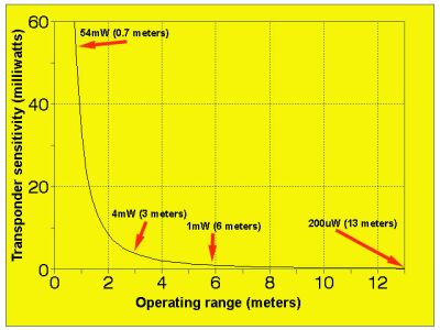
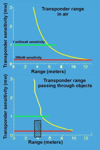 The chart on the left shows how range is effected by goods placed in the path. Two different tag sensitivities are shown, namely 200uW and 1 milliwatt by way of example. As explained above, just by placing the object in the path causes a loss of a large percentage of the power at the boundaries of the object.
In this example, both the 1 mW and the 200uW tags would be able to attached to the far side of the goods and still be read, the 1mW version just having sufficient sensitivity.
The chart on the left shows how range is effected by goods placed in the path. Two different tag sensitivities are shown, namely 200uW and 1 milliwatt by way of example. As explained above, just by placing the object in the path causes a loss of a large percentage of the power at the boundaries of the object.
In this example, both the 1 mW and the 200uW tags would be able to attached to the far side of the goods and still be read, the 1mW version just having sufficient sensitivity.