 Trolley Scan(Pty) Ltd
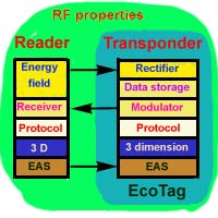
An RFID Transponder system consists of a reader and transponders. The transponder can be as simple as a single integrated circuit attached to a very simple antenna system and costing only a few US cents and yet containing many attractive features.This article explains the different features of the design of such systems.
Introduction.
In 1991 the development of a protocol for Transponder systems has allowed
the development of very low cost transponder systems offering good operating
ranges, and being much lower cost than previous technologies. By operating
in the UHF band (300-3000MHz), antenna systems can be simplified, ranges
are measured in meters and semiconductor technology has advanced to such
a point that all features can be integrated into a single integrated circuit.
Radio frequency based
 RFID
transponder systems make use of the properties of radio frequency propogation.
This allows energy to be radiated from a source and collected by a transponder
which can reply by radiating its response. The performance of the RFID
system will require that the correct RF design methods are used for the
RFID system. It will also require that the systems operate on the correct
operating frequency so that they do not interfere with other users. However
thanks to recent developments, this RF design can be dramatically simplified
and produced at low cost while still being as effective and not causing
interference with other users.
RFID
transponder systems make use of the properties of radio frequency propogation.
This allows energy to be radiated from a source and collected by a transponder
which can reply by radiating its response. The performance of the RFID
system will require that the correct RF design methods are used for the
RFID system. It will also require that the systems operate on the correct
operating frequency so that they do not interfere with other users. However
thanks to recent developments, this RF design can be dramatically simplified
and produced at low cost while still being as effective and not causing
interference with other users.
Energising fields
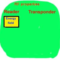 The
transponder system comprises of at least one reader and one transponder.
If a protocol function is provided then the system can comprise of at least
one reader and many transponders.
The
transponder system comprises of at least one reader and one transponder.
If a protocol function is provided then the system can comprise of at least
one reader and many transponders.
In order to keep costs of the transponder down, it is usual to power up
the transponder with its energy requirements from a field radiated by the
reader. This category of transponder system which makes use of the reader's
field powering up the transponders is known as "passive" transponder
systems.
The reader radiates the energising field towards the transponders that
it wishes to power up. The frequency of this radiated energy field will
be set to the operating frequency allocated to the system and the power
radiated will be within the requirements of the regulating authorities
of that region.This is the only critical frequency component in the RFID
system. In many cases different countries will specify widely differing
operating frequencies, and it is desirable for the transponder to operate
correctly at all the likely frequencies it might encounter. This ability
to operate over widely differing frequencies (say 869MHz to 928MHz for
EU/US trade) is called frequency agility. In this situation the
readers that are based in the different countries are set to the allocated
frequency in that country and the transponders respond correctly to any
reader frequency they encounter which is within their operating band.
Powering the transponder
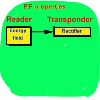 The
transponder collects part of the radiated energtising field via its antenna.
This energy is at the operating frequency of the reader. By using a simple
diode and capacitor circuit, with diodes that are fast enough to operate
at the operating frequency, the energy can be converted to DC voltage and
stored in the capacitor for operating the transponder. More sophisticated
rectifying circuitry can be used, such as full wave rectification or voltage
doubling circuitry if needed.
The
transponder collects part of the radiated energtising field via its antenna.
This energy is at the operating frequency of the reader. By using a simple
diode and capacitor circuit, with diodes that are fast enough to operate
at the operating frequency, the energy can be converted to DC voltage and
stored in the capacitor for operating the transponder. More sophisticated
rectifying circuitry can be used, such as full wave rectification or voltage
doubling circuitry if needed.
Data storage on the transponder
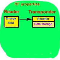 The
transponder requires a series of memory cells to store the data that it
is to broadcast when activated by the reader. This can be in the form or
a read only memory, read/write memory or even the output of sensor systems
contained on the transponder and whose values are to be relayed to the
reader (e.g. electricity meter reading). In some protocols such as Trolleyponder/EcoTag,
all the transponders can contain the same data (e.g identical packets of
Rice Krispies)
The
transponder requires a series of memory cells to store the data that it
is to broadcast when activated by the reader. This can be in the form or
a read only memory, read/write memory or even the output of sensor systems
contained on the transponder and whose values are to be relayed to the
reader (e.g. electricity meter reading). In some protocols such as Trolleyponder/EcoTag,
all the transponders can contain the same data (e.g identical packets of
Rice Krispies)
Transferring data from the transponder to the reader
 The
transponder sends its data back to the reader in serial form. In the 1960's
a development of a technology called backscatter modulation by the
Lawrence Livermore Laboratories in the USA allowed for this communication
to be implimented very simply and at low cost while keeping the required
frequency agile characteristics of the transponder. On the transponder,
a transisitor is switched on and off to vary the load on the antenna of
the transponder in synchronism with the data to be transferred. This varying
of the load changes the antenna matching and causes varying amounts of
the energising field to be reflected back towards the receiver of the reader.
The reader has a simple receiver comprising an antenna for collecting the
returned energy, a mixer, and uses a signal derived from the energising
field as a local oscillator. The data transmitted from the transponder
is available at the output of the mixer for processing in a microprocessor.
The
transponder sends its data back to the reader in serial form. In the 1960's
a development of a technology called backscatter modulation by the
Lawrence Livermore Laboratories in the USA allowed for this communication
to be implimented very simply and at low cost while keeping the required
frequency agile characteristics of the transponder. On the transponder,
a transisitor is switched on and off to vary the load on the antenna of
the transponder in synchronism with the data to be transferred. This varying
of the load changes the antenna matching and causes varying amounts of
the energising field to be reflected back towards the receiver of the reader.
The reader has a simple receiver comprising an antenna for collecting the
returned energy, a mixer, and uses a signal derived from the energising
field as a local oscillator. The data transmitted from the transponder
is available at the output of the mixer for processing in a microprocessor.
Protocols for multiple transponder situations
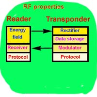 In
the past when transponder's operating range was measured in centimeters,
it was not too important to handle the situation of multiple transponders
as it was difficult to get more than one transponder into the reading zone
at one time. When operating ranges are measured in meters, it is highly
likely that there will be more than one transponder in the zone at a time.
Multiple transponders cause complications as there is only one communications
channel to convey data from the transponders back to the reader, and if
two transponders are communicating at the same time then the receiver detects
a garbled message. Generally it is undesirable for the transponder to have
an onboard receiver itself to detect traffic management instructions being
passed from the reader to the transponders as this introduces cost penalties,
causes temperature stability problems, and means that a single operating
frequency would have to be assigned worldwide if the transponders were
to be used for international trade. The transmission from the transponders
is so weak that other transponders are not able to monitor transmissions
from fellow transponders that might be broadcasting their identity.
In
the past when transponder's operating range was measured in centimeters,
it was not too important to handle the situation of multiple transponders
as it was difficult to get more than one transponder into the reading zone
at one time. When operating ranges are measured in meters, it is highly
likely that there will be more than one transponder in the zone at a time.
Multiple transponders cause complications as there is only one communications
channel to convey data from the transponders back to the reader, and if
two transponders are communicating at the same time then the receiver detects
a garbled message. Generally it is undesirable for the transponder to have
an onboard receiver itself to detect traffic management instructions being
passed from the reader to the transponders as this introduces cost penalties,
causes temperature stability problems, and means that a single operating
frequency would have to be assigned worldwide if the transponders were
to be used for international trade. The transmission from the transponders
is so weak that other transponders are not able to monitor transmissions
from fellow transponders that might be broadcasting their identity.
In 1991 the invention by Mike Marsh published in the patent called Electronic
Identification System described a protocol that could allow a large
number of transponders to be read by a reader without the transponder's
requiring receivers onboard or tuned circuitry. This meant that cheap transponder
systems for multiple transponders were practical. In 1998 Trolley Scan
developed the Trolleyponder protocol, another protocol that could allow
many transponders to be read at the same time with no tuned circuitry.
The protocols are implimented by circuitry in the transponders and the
readers which enable the relative components to manage the traffic and
allow multiple transponders to be read at the same time. The development
of the protocols have been major driving forces behind the sudden massive
acceptance of RFID technology, especially the low cost variety.
Advancements in this field could make RFID technology readily available
like phones, Internet and other applications.
The protocols
are invariably the subject of patents and the solutions need to be licensed.
There are a few other protocols such as treeing, and protocols where
the transponder has onboard receivers to receive back instructions from
the reader or those that only work close to the reader where the reader
can saturate the transponders' tuned circuits.
In the Trolleyponder protocol it is possible to read 1000 transponders
in a zone accurately and quickly, even if they all have identical identity
data, with very simple wide bandwidth transponders.
3 Dimensional scanning
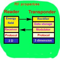 RFID
systems use radio propogations methods to convey energy and data. This
limits their operation to situations where the energy can be transferred
and where communication between the reader and the transponder can be achieved.
One of the characteristics of radio propogation is that the polarisation
of the transponder and the reader must be compatible. A vertically polarised
reader signal will transfer energy to a vertically polarised transponder,
but a vertically polarised reader will not transfer energy to a horizontally
polarised transponder.
RFID
systems use radio propogations methods to convey energy and data. This
limits their operation to situations where the energy can be transferred
and where communication between the reader and the transponder can be achieved.
One of the characteristics of radio propogation is that the polarisation
of the transponder and the reader must be compatible. A vertically polarised
reader signal will transfer energy to a vertically polarised transponder,
but a vertically polarised reader will not transfer energy to a horizontally
polarised transponder.
Should the application have transponders of a known ordered polarisation
then it is possible to correctly orientate the reader to meet the needs
of the application.
However in situations where the transponders are randonly orientated some
of the transponders are likely not to be orientated correctly for efficient
coupling.(e.g supermarket trolley). A recent invention has addressed this
problem by adding some simple circuitry to both the transponder and the
reader to provcvide full 3 dimensional scanning.
Electronic Article Surveillance(EAS)
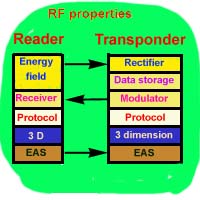 Electronic
Article Surveillance is the technology commonly used in retail systems
to detect unauthorised removal of goods or shoplifting. Electronic Article
Surveillance features come for virtually free in RFID systems and are a
natural extention. By adding a simple one bit memory element to the transponder
and some control circuitry to the reader, EAS features that are fully controllable
are easilty added to the RFID system.
Electronic
Article Surveillance is the technology commonly used in retail systems
to detect unauthorised removal of goods or shoplifting. Electronic Article
Surveillance features come for virtually free in RFID systems and are a
natural extention. By adding a simple one bit memory element to the transponder
and some control circuitry to the reader, EAS features that are fully controllable
are easilty added to the RFID system.
EcoTag
 Different
countries have different regulations regarding the allowable power levels
allowed for RFID applications in the UHF band. In order to get good
operating distances it is necessary to have sufficient power in the energising
field such that the transponder at the operating range receives sufficient
energy to operate. For international trade, it is necessary that the transponders
operate equally well in all countries. Regulations in Europe have set the
maximum power allowed for RFID to approximately two percent of that allowed
in the US. This means that tags that operate reasonably well in the US have
a dismal range in the European Community.
Different
countries have different regulations regarding the allowable power levels
allowed for RFID applications in the UHF band. In order to get good
operating distances it is necessary to have sufficient power in the energising
field such that the transponder at the operating range receives sufficient
energy to operate. For international trade, it is necessary that the transponders
operate equally well in all countries. Regulations in Europe have set the
maximum power allowed for RFID to approximately two percent of that allowed
in the US. This means that tags that operate reasonably well in the US have
a dismal range in the European Community.
The development of the EcoTag principle by Trolley Scan in 1999 addressed
this issue and offers good reading performance in both the EU and US for
UHF tags. EcoTag dramatically increases the energy conversion of the
transponder without compromising the principles of having a single chip
and a simple antenna
Conclusion
Despite the transponder offering the above features, it is practical
today for the transponder to be made in a single integrated circuit for
a few US cents. Readers are also simple and low cost. The technology for
producing these systems is widely available and the barriers to entry for
companies wishing to be producers of low cost transponders have beeen dramatically
lowered compared to past situations.
Trolleyponder®,EcoTag and TinTag are the trademarks of Trolley Scan (Pty) Ltd